Nowadays, electronic security systems, it is at least as important as the functionality. In this paper, by using Arduino microcontroller and control the flow of constant voltage circuit fed from a source similar to the cards we will learn how to. Our goal in a circuit, the load current I constant by monitoring exceeds the specified limits, in the event of a software-controlled flow control system automatically closes the circuit which you create. This traditional insurance through the logic of microcontrollers can be thought of as a digital version.
Such a circuit, especially in the electrical system provides a safety barrier against overcurrent conditions. By opening the circuit excessive current fuses physical components while maintaining that with this project we designed the system more flexible and re-programmable solution. Additionally, the real-time measurements determined by the limits of gives me the opportunity to work at.
Where Available?
- Industrial applications: – Large working machines and engines in industrial environments, devices in order to ensure the safe operation of the current control circuits are widely used. Motors and high current draw devices, when exposed to unwanted current flow increases, this type of system to prevent damage by cutting off the circuit.
- Smart home systems, smart home technologies, devices and automatic control is based on the safe operation. In the House, draws excessive current, the devices of this kind if a digital insurance system, provides security to prevent the interruption of electricity.
- Electric vehicle charging stations for charging electric vehicles, power management systems that are used during overcurrent condition is a very common problem. Arduino-Based current control circuit may provide the vehicles to be charged in a safe manner.
- Hobby electronics and prototype Design, Prototype projects for over-current conditions is an important step to take precautions against. This kind of protection by establishing a system with Arduino, project developers can protect electronic components against excessive current.
- Solar energy systems: solar panels and energy storage systems to avoid overloading the current can be used in control circuits. In these systems, energy management plays a critical role in both panels and battery current control with both safety is ensured.
Current control circuits such excessive current does hamper the flow; it also offers great advantages in terms of energy efficiency and system security. Such a circuit to integrate with the Arduino developers with a flexible and customizable solution. The behavior of this system with software change constantly, and you can adapt different current limits according to the type of load circuit.
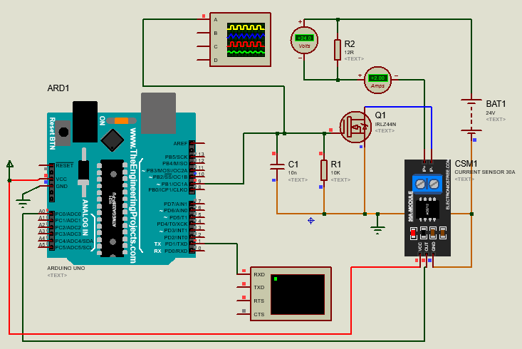
The main purpose of this circuit is the load current and MOSFET current in excess of a specified limit and to check with my Arduino in the case of the power supply is to remove. Now I’ll start by describing the components in the circuit and their functions:

Circuit Components
- Arduino UNO : reads the data from the current sensor and the processing does. If the current exceeds the set limit, disables the MOSFET and load controls.
- R2 Resistance: This is used as the load resistance. There is an inverse relationship between the resistance value and the current in the circuit. So, the resistance value decreases, the current in the circuit increases. 24V constant voltage, in order to attract 12Ω 2A, 1A resistance is used to attract a 24ω.
- (MOSFET IRLZ44N – Q1): This MOSFET, Arduinois triggered by the signal. Arduino, the current exceeds the limit value, the MOSFET is turned off and prevents the passage of the current.
- ACS712 current sensor (CSM1): this sensor measures the current flowing in the circuit and the Arduinoor sends data. Arduino, these data on an ongoing basis and the software monitors the current in the MOSFET is detected when a current that exceeds the limitsthen hangs.
- The capacitor (C1): this element helps to filter out transient voltage fluctuations in the circuit. Is important in terms of the provision of a more stable circuit.
- Resistor R1: MOSFETswitching in the Switch which controls the gate resistance. MOSFETfast and stable operation.
As The Load Resistance In The Circuit Use
In this circuit, we use as the load resistor R2. The currents, the load resistance varies. According to Ohm’s law the current calculation is as follows:
I=V/R
Here, 24V voltage V is constant and R is the load resistance. The sample table is as follows:
| Direnç (R) | Akım (I) |
|---|---|
| 24Ω | 1A |
| 12Ω | 2A |
| 6Ω | 4A |
| 2.4 Ω | 10A |
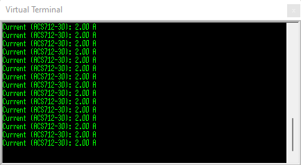
According to this table, when the value of resistance increases the current in the circuit drop. Applied to the circuit corresponds to a voltage of 24V, 12Ωresistor when used in a circuit will flow 2A.
Working Principle
- Current sensor Readings: Arduino, sensor ACS712 current flows continuously takes measurements. This sensor transmits current through the circuit Arduino turning it into an analog signal.
- Current limiting: current limit specified in the program is controlled by the software Arduino. For example, the system is limited to 4A and 4A flow in the circuit when the load exceeds the Arduino detects this situation and stops the passage of current by turning off the MOSFET. Thus, the safety of the circuit is ensured.
- MOSFET Control: Arduino, sensors MOSFET according to the data ofi controls. In case of exceeding the specified limits, MOSFET interrupts the transmission. Thus, the pull of the load will prevent too much current.
- Re-runthe current stable boundaries (when you change the load, or when a problem have been resolved), again by passing to the conduction of MOSFETs the circuit Arduino runs.
In this way, the circuit to be protected from excessive currents can be ensured. Both hardware and software components working together, this creates a security mechanism.

Detailed Description Of The Code
Our code fulfills two main functions: first continuously monitor flow, and the second exceeds the current limit, the PWM signal in the circuit by interrupting the passage of power stop.
The Complete Code
const int analogInPin = A0;  // Analog giriş pini
const float sensitivity = 0.066;  // ACS712-30 için hassasiyet faktörü (66 mV/A)
const float currentLimit = 2.0;  // Akım sınırı (2A)

void setup() {
  // PWM için portları ayarla
  DDRB |= (1 << DDB1) | (1 << DDB2);                     // PB1 (OC1A) ve PB2 (OC1B) çıkış pinleri olarak ayarlanıyor

  // Timer1'i Fast PWM modu, yüksek frekans için yapılandır
  TCCR1A = (1 << COM1A1) | (1 << COM1B1) | (1 << WGM11); // Fast PWM, OC1A/OC1B karşılaştırma eşleşmesinde temizle, tabanda ayarla
  TCCR1B = (1 << WGM12) | (1 << WGM13) | (1 << CS10);    // Fast PWM, ön ölçekleme yok (CS10 = 1), maksimum frekans

  ICR1 = 1600;  // PWM periyodunu ayarla, küçük değer = daha yüksek frekans
  OCR1A = 1600; // %50 duty cycle ile başla (ICR1'in yarısı)

  Serial.begin(9600);  // Seri monitörle iletişimi başlat

}

void loop() {
  int sensorValue = analogRead(analogInPin);  // Akım sensörü değerini oku
  // Sensörden gelen değeri voltaja ve sonra akıma çevir
  float current = ((sensorValue - 512) * (5.0 / 1023.0)) / sensitivity;

  // Akımı seri monitöre yazdır
  Serial.print("Measured Current: ");
  Serial.print(current);
  Serial.println(" A");

  // Eğer akım 2A'den büyükse PWM çıkışını kapat (MOSFET'i kapat)
  if (current > currentLimit) {
    OCR1A = 0;  // PWM duty cycle'ı sıfırla, MOSFET kapalı
    Serial.println("Current exceeded limit! Power cut.");
  } else {
    OCR1A = 1600;  // Duty cycle'ı %100 olarak ayarla, MOSFET açık
    Serial.println("Current is within limit.");
  }

  delay(500);  // Akım ölçüm ve kontrol döngüsü için gecikme
}
1. Define The Variables:
const int analogInPin = A0;  // Analog giriş pini
const float sensitivity = 0.066;  // ACS712-30 için hassasiyet faktörü (66 mV/A)
const float currentLimit = 2.0;  // Akım sınırı (2A)
analogInPin: the signal from the current sensor ACS712 Arduinoanalog input pin A0 of we’ll read from.sensitivity: This ACS712-30 sensitivity of the current sensor. This sensor 66mV/A works with precision, so every 66mV per Ampere voltage produces.currentLimit: has been identified as 2A current limit. If the current in the circuit exceeds this value, the MOSFETof the closure is ensured.
2. the setup() Function:
void setup() {
  DDRB |= (1 << DDB1) | (1 << DDB2);                     // PB1 (OC1A) ve PB2 (OC1B) çıkış pinleri olarak ayarlanıyor

  // Timer1'i Fast PWM modu, yüksek frekans için yapılandır
  TCCR1A = (1 << COM1A1) | (1 << COM1B1) | (1 << WGM11); // Fast PWM modu
  TCCR1B = (1 << WGM12) | (1 << WGM13) | (1 << CS10);    // Ön ölçekleme yok

  ICR1 = 1600;  // PWM periyodunu ayarlamak için TOP değeri
  OCR1A = 1600; // PWM duty cycle %50 başlangıç

  Serial.begin(9600);                                    // Seri haberleşmeyi başlat
}

- PWM Settings: in this section by using the Timer1 PWM signal is produced. Timer1, mode is set to fast PWM and MOSFETwith PWM signal to be sent to the E to control the load on the circuit is provided.
- And ICR1 OCR1A: these two registers (register), PWM frequency and duty cycle of the signalis checking ini.
ICR1 = 1600;line PWM period setting whenOCR1A = 1600;duty cycle lineset up. With these settings, initially PWM signal with 50% duty cycle was initiated. - Serial.begin(9600): serial communication between an Arduino and a computer starts. In this way, current measurements, and other outputs from the serial monitor we can observe.
3. loop() Function:
void loop() {
  int sensorValue = analogRead(analogInPin);  // Akım sensörü değerini oku
  float current = ((sensorValue - 512) * (5.0 / 1023.0)) / sensitivity;

  Serial.print("Measured Current: ");
  Serial.print(current);
  Serial.println(" A");

  // Eğer akım 2A'den büyükse PWM çıkışını kapat
  if (current > currentLimit) {
    OCR1A = 0;  // PWM duty cycle'ı sıfırla, MOSFET kapalı
    Serial.println("Current exceeded limit! Power cut.");
  } else {
    OCR1A = 1600;  // Duty cycle'ı %100 olarak ayarla, MOSFET açık
    Serial.println("Current is within limit.");
  }

  delay(500);  // Akım ölçüm ve kontrol döngüsü için gecikme
}
analogRead()and the current Calculation: this function reads the acs712 current sensor converts the analog signal from the signal. Conversion process is done with the following formula:
float current = ((sensorValue - 512) * (5.0 / 1023.0)) / sensitivity;
sensorValue, Arduino’s analog pin value is read on. 512, reference values are given in the zero current sensor (ACS712 thecalibration depends on). 5.0/1023.0, Arduinoanalog reading of the resolution (5V, 10-bit ADC). This value is used to calculate the voltage from the sensor, then the voltage is converted to current by dividing the value of the sensitivity of the sensor.
- The current values printed to the serial monitor: serial monitor the value of the measured current in each loop is printed. In this way, you can follow the measurements.
- Control of the current limit: if the measured current exceeds 2 amps:
if (current > currentLimit) {
    OCR1A = 0;
    Serial.println("Current exceeded limit! Power cut.");
}
In this case, the PWM duty cycle is reset to zero, the MOSFET turns off and the current in the circuit is cut off. If the current limit is below the PWM signal at 100% duty cycle, continues:
OCR1A = 1600; // Duty cycle'ı %100 olarak ayarla, MOSFET açık
- Delay: Cycle is executed every 500 milliseconds. This delay provides the current value of the observation in orderly and readable way.
The Result Of The Project
2A with Arduino and acs712 sensor this codewhen necessary to protect the circuit of MOSFET current limit monitors andthen hangs. This electronic projects especially in an over-current condition is important for the Prevention of an application. Arduino PWM control and current limit on the code ensures the safe operation of a circuit.
Development and application fields
This system can be used in larger projects:
- Battery protection: Excessive current draw for devices that can be used to separate batteries.
- Electric motors: the motor load is suited to deactivate a specific trend.
- Sources of power: constant current limit circuits to prevent damage to the power management systems may be using.
This project is quite easy to adapt to different applications. For example, the current limit is higher or lower by changing the current boundaries so that you can monitor and protect the circuit can identify the different loads.
